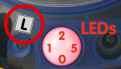
LED Standard Functions:
- LED 0: Power
- LED 1: Image processing/Event
- LED 2: Ethernet
- LED 3: Serial (RS232)
- LED 4: VoIP/ISDN
- LED 5: Image processing/Event

MOBOTIX cameras can have up to six LEDs on the front (depending on the camera model) to inform you about different actions/states of the system. Open the LED Setup dialog to modify LED behavior or to deactivate them entirely.
| Note: | Open the General Event Settings dialog to modify the behavior of the LEDs that have been set to Event in this dialog. |
|---|
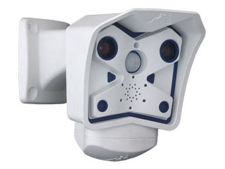
The MOBOTIX M12 has six LEDs:
|
LED Standard Functions:
|
|
|
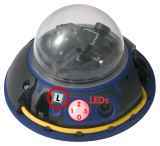
The MOBOTIX D12 has four LEDs:
|
LED Standard Functions:
|
 |
 |
The MOBOTIX M22M has two LEDs:
|
LED Standard Functions:
|
 |
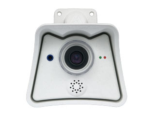 |
The MOBOTIX D22M has two LEDs:
|
LED Standard Functions:
|
 |
 |
| Parameter | Description | ||||||||
|---|---|---|---|---|---|---|---|---|---|
| LED Main Switch |
The main switch activates or deactivates all LEDs of the camera.
|
||||||||
| Set all LEDs |
You can assign the same function to all LEDs:
All other options correspond to the functions that you can select for the individual LEDs. For more detailed information, see the LED Signals help page.
|
You can assign a different signaling function to every LED:
| Signal | Meaning | ||
|---|---|---|---|
| on | The LED is on without interruption. | ||
| Off |
The LED's signal feature is deactivated during regular operation.
|
||
| Web Access | The LED lights up when the camera's web server is being accessed. | ||
| Accessing Live Images | The LED lights up when the camera's live image is being accessed. | ||
| Blink | The LED blinks slowly. | ||
| Flash | The LED blinks rapidly. | ||
| event | The LED signals events as set by the LEDs parameter in the General Event Settings dialog (you may have to click More to display this parameter). | ||
| Left button | The LED lights up when you press the L key on the camera's front. | ||
| Right button | The LED lights up when you press the R key on the camera's front. | ||
| Networking | The LED signals activity on the Ethernet interface. | ||
| Camera | The LED shows the activity of the image sensors. Slow blinking indicates long exposure times. | ||
| VoIP/ISDN |
The LED signals activity on the ISDN interface or a VoIP connection. LED Signals When in VoIP Mode:
If a voice connection has been established via the VoIP (SIP) or ISDN interfaces, the LEDs signal the following:
|
||
| PIR | The LED indicates if an event has been triggered by the passive infrared detector. | ||
| Signal Input | The LED lights up when the signal input is active. | ||
| Signal output | The LED lights up when the signal output is active. | ||
| Serial interface | The LED signals activity on the serial (RS232) interface. |
| Note: | The option at the top is always the default option that is used if Set all LEDs has been set to Default. |
|---|
| PIR Threshold |
Define the trigger level for the passive infrared detector.
|
|---|
Click on the Set button to activate your settings and to save them until the next reboot of the camera.
Click on the Close button to close the dialog. While closing the dialog, the system checks the entire configuration for changes. If changes are detected, you will be asked if you would like to store the entire configuration permanently.
| de, en |